
On and off symbols appear everywhere, from household appliances to computers, televisions, and industrial machines. Yet these tiny markings can cause surprising confusion. Is the circle ON or OFF? Does the vertical line mean power is running? What does the circle with a line through it represent?
Understanding on and off symbols makes everyday technology easier to use. It also helps you recognize power controls, interpret electrical markings, and distinguish complete shutdown from standby mode.
The basic rule is simple: I or a vertical line (|) represents ON, while O or a circle represents OFF. However, combined power symbols and standby markings communicate different functions.
This guide explains the meanings of common power symbols, their international standards, electrical applications, and practical uses. You’ll also find a copy-and-paste symbol chart and answers to frequently asked questions.
What Are On and Off Symbols?
On and off symbols are graphical markings that communicate whether electrical equipment is operating, switched off, or placed in a particular power state. Manufacturers use them on physical switches, electronic buttons, control panels, and household appliances.
These markings provide a simple visual language. Instead of translating words such as ON and OFF into dozens of languages, manufacturers can use familiar symbols that communicate the same basic instructions.
For example, you might find a vertical line and circle on a computer power supply. A washing machine may display similar markings beside its main control. A television remote might use a combined power icon.
The most recognizable on and off signs include:
- I or |: Represents the ON position.
- O or ○: Represents the OFF position.
- ⏻: Represents a combined power control.
- ⏼: Represents a standardized combined ON/OFF control.
- ⏽: Represents a power-on marking.
- ⏾: Represents a sleep-related function.
- 1 and 0: Commonly represent binary ON and OFF states.
The International Electrotechnical Commission (IEC) maintains a collection of standardized graphical symbols for electrical and electronic equipment. Its IEC 60417 database provides identification numbers and descriptions for many familiar equipment markings.
These standards help manufacturers create recognizable controls across different products and countries.
On and Off Symbols and Their Meanings
The easiest way to understand on and off symbols meaning is to compare their appearances and functions.
| Symbol | Name | Meaning |
| I | Letter I / vertical-line marking | ON |
| | | Vertical line | ON |
| O | Letter O / circle marking | OFF |
| ○ | Open circle | OFF |
| ⏻ | Combined power symbol | Power control |
| ⏼ | Combined ON/OFF symbol | ON/OFF control |
| ⏽ | Power-on symbol | ON |
| ⏾ | Sleep symbol | Sleep-related state |
| 1 | Binary one | Commonly represents ON |
| 0 | Binary zero | Commonly represents OFF |
Important: These symbols don’t all perform the same function. Some identify a switch position while others represent a control or operating state.
I or Vertical Line Symbol (ON)
I or | = ON
The vertical line is the standard marking for the power-on symbol. When you see it on an electrical switch, it identifies the ON position.
The symbol connects to the number one in binary notation. In basic digital logic, 1 commonly represents an active or high state while 0 represents an inactive or low state.
The IEC identifies the equipment marking for ON with reference number 5007 in IEC 60417.
You’ll commonly find the vertical-line marking on:
- Desktop computer power supplies.
- Monitor switches.
- Extension strips and power strips.
- Household appliances.
- Industrial control panels.
- Audio equipment.
- Electronic testing equipment.
On a traditional rocker switch, pressing the side marked I usually activates the switch. However, always check the actual markings because installation and switch orientation can vary.
O or Circle Symbol (OFF)
O or ○ = OFF
The circle represents the OFF symbol. It identifies the position that switches equipment off through the relevant power control.
The circle resembles the number zero. This connection makes the marking easier to understand because zero commonly represents an inactive state in binary notation.
The IEC identifies the standardized equipment marking for OFF as IEC 60417-5008.
You may see the circle marking on:
- Kitchen appliances.
- Computer power supplies.
- Electrical switches.
- Industrial machinery.
- Power distribution equipment.
- Audio and video devices.
When a rocker switch shows I on one side and O on the other, the markings identify its two operating positions.
One important distinction: switching a device OFF doesn’t always disconnect every internal circuit from its electrical supply. Some equipment retains standby functions or other energized components.
Combined Circle and Line Power Symbol
⏻ = Combined Power Symbol
The familiar power button symbol combines the visual ideas of a circle and vertical line. You’ll recognize it from computers, televisions, smartphones, gaming consoles, and countless other electronic devices.
The combined symbol represents a power-control function. However, its precise operation depends on the equipment and the type of switch.
For example:
- A computer’s power button may start the machine with one press.
- A television’s power button may switch between operation and standby.
- A gaming console may enter a low-power state instead of disconnecting completely.
- An electronic appliance may use the symbol for a maintained ON/OFF control.
The IEC identifies a standardized push-push ON/OFF equipment marking as IEC 60417-5010.
This is an important distinction. A combined power graphic isn’t automatically an indication that a device has been completely disconnected from electricity.
Standby and Sleep Symbols
Standby and sleep markings describe reduced-power states rather than ordinary ON or OFF positions.
The standby symbol (⏻-related marking) is commonly recognized by its partial-circle appearance with a vertical line. Its standardized IEC equipment reference is 60417-5009.
A standby device may retain enough power to respond to remote controls, scheduled operations, network signals, or wake-up commands.
For example, a television in standby may display a small red indicator light. Although the screen is dark, some internal electronics remain active.
Sleep mode is related but isn’t always identical. A computer in sleep mode can preserve its session in memory while reducing power consumption.
The main differences are:
- ON: The equipment performs its normal operating functions.
- OFF: The equipment’s normal operation stops.
- Standby: Selected circuits remain available for quick activation.
- Sleep: The device enters a reduced-power state while preserving certain functions or information.
Don’t assume every manufacturer uses these terms in precisely the same way.
Is the Circle or Line ON or OFF?
The answer is straightforward:
- Line (I or |) means ON.
- Circle (O or ○) means OFF.
These markings come from the familiar relationship between one and zero in binary notation. The vertical line represents one while the circle represents zero.
However, the physical arrangement of a switch can sometimes make the markings confusing.
Does a Circle Mean ON or OFF?
A circle means OFF when it appears as the standardized OFF marking on a power switch.
People sometimes mistake it for the letter O. Others assume the circle represents a complete electrical loop, suggesting that electricity can flow through a circuit.
Neither interpretation changes the standardized marking’s meaning.
On an ordinary I/O rocker switch:
- Press the I side to turn the switch ON.
- Press the O side to turn the switch OFF.
Always check the manufacturer’s markings when the switch design looks unfamiliar.
Which Side of a Rocker Switch Is ON?
Most traditional rocker switches display I and O on opposite ends.
The side marked I identifies the ON position. The side marked O identifies the OFF position.
For example, a computer power supply might have a small rocker switch near its power cable connection. Pressing the I side activates its main power switch while pressing O disconnects that switched supply.
However, don’t assume the ON position is always on the right or top. Manufacturers install switches in different orientations.
Read the symbols rather than relying on their physical direction.
How Can You Tell Whether a Device Is ON or OFF?
A device doesn’t always communicate its power state through its switch position alone. Some electronics have separate indicators for power, charging, network activity, and standby.
Use these practical checks:
- Inspect the power switch: Look for I, O, or a combined power marking.
- Check the indicator light: A lit LED may indicate operation or standby.
- Look at the display: An active screen often indicates that the device is operating.
- Test the controls: Check whether the equipment responds normally.
- Consult the manual: Manufacturer instructions explain unusual indicators and power states.
Remember that an illuminated indicator doesn’t always mean the device is fully ON. It might simply show that standby power remains available.
Different Types of On and Off Switch Symbols
Not every power control works in the same way. Some switches maintain a position while others activate only when you press them.
Understanding these differences helps you identify the correct on/off switch symbols on electronic equipment.
Separate ON and OFF Symbols
Separate markings use individual symbols to identify the two positions of a physical switch.
The most common arrangement includes:
- I: Power ON.
- O: Power OFF.
These markings commonly appear on power supplies, appliances, extension boards, and industrial equipment.
A two-position rocker switch usually maintains whichever position you select. Once you press I, the switch stays ON until you press O.
This design makes the power state easy to identify without checking a screen or indicator light.
Combined ON/OFF Switch Symbols
A combined marking communicates that one control can change between two power states.
The standardized symbol ⏼ is called the power ON-OFF symbol in Unicode. It corresponds to IEC 60417-5010.
This symbol is particularly relevant to push-push switches. These controls have two stable positions: one ON and one OFF.
For example, a desktop computer might use a maintained mechanical power control. Pressing it once activates the switch while pressing it again returns it to the OFF position.
However, modern electronic power buttons often behave differently. Their software may control shutdown, sleep, or standby rather than directly disconnecting the electrical supply.
Momentary Power Button Symbols
A momentary power button works only while the control is being pressed or through an electronic action triggered by pressing it.
The IEC identifies this type of control with symbol 5011, called ON/OFF (push button).
Its operation differs from a maintained rocker switch.
| Feature | Maintained switch | Momentary button |
| Position | Remains in selected position | Returns after release |
| Operation | Maintains electrical state | Triggers an action |
| Common example | Mechanical power switch | Computer power button |
| Control behavior | Physical switching | May involve electronic logic |
Consider a laptop power button. A quick press may wake the computer while holding the same button longer may trigger a shutdown. The operating system and manufacturer determine the exact behavior.
Standby Power Symbols
Standby is one of the most misunderstood power symbols.
The symbol ⏻ has the Unicode name POWER SYMBOL. Unicode also identifies it with the IEC 5009 standby symbol.
This distinction matters because people often call every circle-and-line graphic a universal ON/OFF button.
According to the IEC description, the standby marking identifies a control or switch position that brings equipment into a standby condition. It can also identify a low-power state.
The symbol ⏼, meanwhile, represents the power ON/OFF function associated with IEC 5010.
Unicode lists these different names and relationships in its official character chart.
Unicode+2
What Is the Difference Between ON, OFF, and Standby?
The words ON, OFF, and standby describe different operating conditions. Knowing their differences prevents confusion when using modern electronics.
| Power state | Electrical condition | What happens |
| ON | Equipment receives operating power | Normal functions are available |
| OFF | Main switched power is disconnected | Normal operation stops |
| Standby | Selected circuits remain powered | The device can respond to certain commands |
| Sleep | Reduced-power operating condition | The device may preserve its session and resume quickly |
Power ON vs. Power OFF
When equipment is ON, its main operating functions receive the power they need.
A television displays content. A computer runs its operating system. A microwave can operate its cooking functions.
When equipment is switched OFF through its main power switch, the relevant electrical supply is disconnected.
However, the exact meaning depends on the equipment’s design. An electronic OFF command may stop normal operation without physically disconnecting the device from mains electricity.
This distinction becomes especially important when working with electrical equipment.
Power OFF vs. Standby
Standby allows equipment to remain partially active while reducing energy consumption.
For example, a television in standby may continue powering its remote-control receiver. It can respond when you press the remote’s power button.
Other standby functions may include:
- Network connectivity.
- Scheduled updates.
- Wake-up commands.
- Clock and timer functions.
- Remote-control reception.
- Background maintenance.
The device isn’t performing its normal operating functions. However, some internal circuits remain energized.
The IEC’s description of symbol 5009 specifically connects standby with a low-power condition.
OMRON Healthcare – OMRON Healthcare, Inc.+1
Standby vs. Sleep Mode
Sleep mode and standby mode both reduce power consumption. However, manufacturers may use these terms for different operating conditions.
A laptop in sleep mode generally preserves its active session so you can resume work quickly. Depending on the system, it may retain information in memory or use another low-power mechanism.
A television in standby may instead wait for a remote-control signal.
Here’s a practical comparison:
| Feature | Standby | Sleep |
| Main purpose | Wait for activation | Pause normal activity |
| Power consumption | Usually reduced | Usually reduced |
| Remote activation | Often available | Depends on device |
| Session preservation | Device-dependent | Common on computers |
| Typical equipment | TVs and audio systems | Laptops and computers |
Neither term automatically means zero electricity consumption. Check the manufacturer’s specifications for exact behavior.
How Do On and Off Symbols Work in Electrical Circuits?
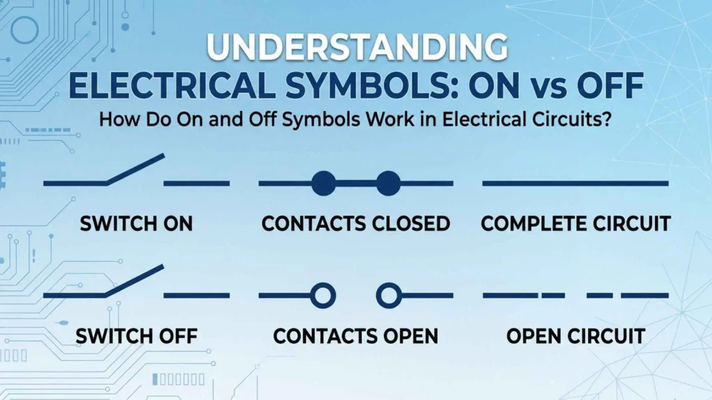
The relationship between on and off symbols electrical markings and circuit operation becomes clearer when you understand how switches control current.
An electrical circuit provides a path through which electrical current can flow. A switch changes the continuity of that path.
A basic circuit contains:
- A power source.
- Conducting wires.
- A switch.
- An electrical load.
- Appropriate protective components.
For example, a simple flashlight contains a battery, switch, wires, and light source. Operating the switch changes whether the circuit can deliver power to the bulb.
Open Circuit and Closed Circuit
An open circuit has an interrupted conducting path. In a basic series circuit, this prevents normal current flow.
A closed circuit has a complete conducting path that allows current to flow when a suitable voltage source is connected.
| Circuit condition | Description | Typical result |
| Open circuit | Conducting path is interrupted | Current stops in the affected path |
| Closed circuit | Conducting path is complete | Current can flow |
| Short circuit | An unintended low-impedance path exists | Potentially dangerous excessive current |
These terms help explain mechanical switches.
For a simple normally open lighting switch:
- Switching ON closes the circuit.
- Switching OFF opens the circuit.
However, don’t assume every electrical system follows this exact arrangement. Electronic controls, relay circuits, and safety systems can behave differently.
How an Electrical Switch Controls Current
An electrical switch controls whether current can travel through a particular circuit path.
Inside a mechanical switch, conductive contacts move together or apart.
When the contacts close, they complete the electrical connection. When they open, they interrupt that connection.
Different switch designs use different mechanisms:
- Rocker switches: A pivoting control changes the contact position.
- Toggle switches: A lever changes between operating positions.
- Push-button switches: Pressing the button activates a mechanical or electronic action.
- Rotary switches: Turning a knob selects different electrical connections.
- Slide switches: Sliding a control changes the connection.
The external marking helps users understand the intended operation. The internal mechanism determines how the switch actually controls the circuit.
How Digital Electronics Use ON and OFF States
Digital electronics use binary information to represent data and control operations.
Binary notation uses two digits:
- 1: Commonly represents a logical HIGH or active state.
- 0: Commonly represents a logical LOW or inactive state.
These states form the foundation of digital logic.
Computers use billions of electronic switching elements called transistors. Their electrical behavior helps circuits process and store binary information.
However, logical 1 and 0 aren’t always equivalent to a device’s physical ON and OFF conditions.
For example, a digital circuit can use an active-low signal. In that arrangement, a logic value of 0 activates a particular function.
Therefore, the relationship between binary code and power symbols is useful but shouldn’t be treated as a universal electrical rule.
What Do On and Off Symbols Mean in Wiring Diagrams?
On and off symbols wiring questions often involve a different kind of marking.
Equipment power symbols identify controls and operating states. Wiring diagrams show electrical connections and component relationships.
These are related subjects, but they aren’t interchangeable.
A wiring diagram may contain:
- Switch contacts.
- Electrical conductors.
- Power sources.
- Ground connections.
- Fuses.
- Relays.
- Motors.
- Lamps.
- Connectors.
- Protective devices.
Electrical engineers use these drawings to design, install, inspect, and troubleshoot equipment.
Normally Open (NO) Switches
A normally open switch has contacts that remain disconnected in their normal, unactuated condition.
When someone operates the switch, its contacts close and complete the circuit.
For example, a simple doorbell button often uses a normally open contact. Pressing it completes the circuit and activates the bell.
Common applications include:
- Doorbell buttons.
- Start controls.
- Push-button inputs.
- Certain sensor circuits.
- Machine activation controls.
The word normally describes the switch’s default mechanical condition. It doesn’t necessarily mean the entire machine is normally OFF.
Normally Closed (NC) Switches
A normally closed switch has contacts that remain connected in their normal, unactuated condition.
Operating the switch opens the contacts and interrupts the circuit.
Common examples include:
- Certain stop controls.
- Limit switches.
- Position-detection systems.
- Some safety interlock arrangements.
NC contacts can help control equipment safely. However, their presence alone doesn’t guarantee a complete safety system.
Industrial safety circuits require suitable components, design, testing, and maintenance.
Power Switch Symbols in Electrical Schematics
A schematic uses standardized graphic conventions to represent electrical components and their relationships.
A switch symbol may show whether its contacts are normally open or normally closed.
This differs from an equipment marking such as I or O.
| Term | What it identifies |
| I / ON | Power-on switch position |
| O / OFF | Power-off switch position |
| NO | Normally open contact |
| NC | Normally closed contact |
| Standby | Reduced-power equipment state |
| Ground | Electrical reference or protective connection, depending on the symbol |
When reading a schematic, always check its legend and accompanying documentation. The same physical device may have several different representations across drawings and equipment labels.
Where Are On and Off Symbols Used?
The universal on and off symbols appear across many industries because people need recognizable controls on different types of equipment.
Their practical applications extend far beyond ordinary household switches.
Computers and Laptops
Computers use power symbols on both external switches and electronic controls.
Desktop computers may have a front-panel power button and a separate power-supply switch at the back.
These controls can perform different functions.
For example:
- The front button starts the computer.
- A short press may request an operating-system shutdown.
- A longer press may force a shutdown, depending on configuration.
- The rear power-supply switch can disconnect the switched mains input.
Laptops commonly use a combined power marking on their keyboard or chassis.
Some models also use the same button to wake the device from sleep.
Smartphones and Tablets
Smartphones and tablets commonly use a side-mounted power button.
Depending on the operating system and manufacturer, this button may:
- Wake the screen.
- Lock the device.
- Turn off the display.
- Open a shutdown menu.
- Restart the device.
- Activate an assigned shortcut.
A phone’s power button doesn’t necessarily disconnect its battery. It controls the device’s operating state through its internal electronics.
Televisions and Remote Controls
Televisions commonly display the combined power symbol on their remote controls and physical buttons.
Pressing it may turn the television on or place it in standby.
Some televisions maintain network connectivity while in standby. This allows selected smart features to remain available.
Always check the manufacturer’s settings if you want to disable background connectivity or reduce standby consumption.
Household Appliances
Household appliances use power markings to simplify everyday operation.
Common examples include:
- Washing machines.
- Microwaves.
- Refrigerators.
- Coffee makers.
- Electric kettles.
- Fans.
- Air conditioners.
- Dishwashers.
A washing machine may use a combined power control to activate its electronic interface. A microwave may use separate power and cooking controls.
An appliance’s power button also differs from its START, STOP, and RESET controls. Each performs a specific task.
Audio Equipment and Gaming Devices
Audio and entertainment equipment uses recognizable power markings on many controls.
Examples include:
- Bluetooth speakers.
- Headphones.
- Amplifiers.
- Soundbars.
- Gaming consoles.
- Home theater receivers.
- Portable music players.
A Bluetooth speaker might use a long press to switch power states. A gaming console might use a brief press to enter standby.
The physical icon can look similar even though the underlying functions differ.
Industrial Equipment and Control Panels
Industrial machines use standardized control markings to help operators identify equipment functions.
You’ll find power controls on:
- Manufacturing machinery.
- Generators.
- Laboratory equipment.
- Pumps.
- Compressors.
- Production-line control panels.
- Electrical distribution equipment.
- In these environments, clear labeling is especially important. An incorrect operation can interrupt production or create a safety hazard.
Power controls must also remain distinct from emergency stop controls. An ordinary OFF button doesn’t automatically provide the safety function of an emergency stop.
Vehicles and Electric Vehicles
Modern vehicles use electronic controls for starting and stopping their power systems.
Many cars have push-button ignition systems with START/STOP markings.
Electric vehicles also use electronic controls to activate or deactivate their driving systems.
However, vehicle controls shouldn’t be confused with ordinary appliance power buttons.
A car’s power mode may involve accessories, ignition electronics, high-voltage systems, and other components. Follow the vehicle manufacturer’s instructions when operating or servicing these systems.
History of the Universal Power Button Symbol
The familiar power button graphic has become one of the most recognizable symbols in modern technology. Its widespread use reflects the need for simple, consistent equipment controls.
Before graphical symbols became common, manufacturers relied heavily on written labels and product-specific markings. This created challenges when equipment crossed language and national boundaries.
A standardized visual marking offered a practical solution.
Why Did Manufacturers Need Universal Power Symbols?
Electronic products are sold across international markets. A television manufactured in one country may be used in another where consumers speak a different language.
Written labels such as ON, OFF, START, and STOP aren’t equally familiar to everyone.
Graphical symbols help reduce this communication barrier.
Manufacturers benefit from standardized markings because they can:
- Reduce the need for translated control labels.
- Make equipment easier to recognize.
- Improve consistency across product ranges.
- Help users identify important functions.
- Support international product distribution.
However, a symbol’s familiarity doesn’t eliminate the need for clear instructions. Manufacturers still need appropriate labels, manuals, and safety information.
The Role of the International Electrotechnical Commission (IEC)
The International Electrotechnical Commission (IEC) develops international standards for electrical, electronic, and related technologies.
One important resource is IEC 60417, which contains graphical symbols used on equipment.
The database includes more than 1,400 symbols covering equipment identification, functional states, connections, and operating instructions. The IEC lists its current 2026 database edition as IEC 60417:2026 DB.
IEC+1
Some important power-related references include:
| IEC reference | Official description |
| 5007 | ON (power) |
| 5008 | OFF (power) |
| 5009 | Standby |
| 5010 | ON/OFF (push-push) |
| 5011 | ON/OFF (push button) |
| 5264 | ON for part of equipment |
| 5265 | OFF for part of equipment |
| 5266 | Standby or preparatory state for part of equipment |
These identification numbers help manufacturers and engineers refer to specific graphical markings without relying on informal descriptions.
iTeh Standards+1
Why Is the Power Button Symbol Recognized Worldwide?
The power symbol benefits from repeated exposure. People encounter it on phones, computers, appliances, vehicles, and entertainment equipment.
Over time, its appearance becomes familiar even when users don’t know its official name.
Several factors support its recognition:
- Consistent appearance: Standardized designs reduce confusion.
- Simple geometry: Basic shapes are relatively easy to recognize.
- Repeated exposure: Common devices reinforce recognition.
- International use: Manufacturers distribute similar controls worldwide.
- Minimal text: Graphical controls reduce dependence on language.
The result is a familiar visual language that helps people operate modern equipment.
How to Use and Recognize On and Off Symbols Safely
Recognizing on and off symbols is useful, but understanding their limits is equally important.
A power marking tells you about a control or operating state. It doesn’t necessarily prove that equipment is electrically safe to open, repair, or touch internally.
Check the Markings Before Operating a Switch
Before using an unfamiliar electrical control, inspect its markings.
Look for:
- I or | for ON.
- O or ○ for OFF.
- ⏻ for standby-related power control.
- ⏼ for combined ON/OFF control.
- Manufacturer-specific operating indicators.
If the switch doesn’t have recognizable markings, consult the equipment manual.
Don’t guess based on whether the switch is positioned upward, downward, left, or right.
Understand the Difference Between OFF and Electrical Isolation
One of the most important electrical safety lessons is that OFF doesn’t always mean electrically isolated.
A device can stop operating while remaining connected to its power source.
For example, switching off a television through its remote may leave standby electronics energized. Turning off a computer through its operating system doesn’t necessarily disconnect its power supply from the mains.
Electrical isolation requires an appropriate method designed for the equipment.
Depending on the system, this may involve:
- Disconnecting the power plug.
- Operating a suitable isolating switch.
- Following an approved lockout/tagout procedure.
- Verifying that electrical energy has been removed.
- Allowing stored energy to discharge according to manufacturer instructions.
Some equipment contains capacitors, batteries, or other energy-storage components. These can retain hazardous energy after the main supply is disconnected.
Never open electrical equipment simply because its power indicator shows OFF.
For electrical repairs, use a qualified professional when the work involves hazardous voltages or unfamiliar equipment.
Recognize Emergency Shutoff Controls
An emergency stop control serves a different purpose from an ordinary power button.
Its job is to stop a dangerous machine operation or reduce a hazard when an emergency occurs.
Emergency controls often have distinctive designs and markings. In industrial settings, their appearance and placement follow applicable safety standards.
| Control | Main purpose |
| Power ON | Activates equipment |
| Power OFF | Stops normal operation |
| Emergency STOP | Stops hazardous operation in an emergency |
| Reset | Restores a system or clears a fault when permitted |
| Isolator | Separates equipment from an energy source |
Don’t use these terms interchangeably. A machine’s ordinary power button may not provide the protective function of its emergency stop system.
On and Off Symbols Copy and Paste
Looking for power symbols copy and paste options? The following chart includes commonly used characters and their meanings.
You can copy these symbols into documents, presentations, website content, messages, and design projects.
| Symbol | Name | Meaning |
| I | Letter I | ON marking |
| | | Vertical line | ON marking |
| O | Letter O | OFF marking |
| ○ | White circle | Circle-shaped OFF marking |
| ⏻ | Power symbol | Standby-related symbol |
| ⏼ | Power ON-OFF symbol | Combined ON/OFF |
| ⏽ | Power ON symbol | ON |
| ⏾ | Power sleep symbol | Sleep |
| 1 | Binary one | Common logical ON state |
| 0 | Binary zero | Common logical OFF state |
A technical distinction worth remembering: The Unicode names aren’t identical to informal descriptions commonly found online.
According to the Unicode character chart:
- ⏻ (U+23FB): POWER SYMBOL; associated with IEC 5009 standby and IEEE 1621.
- ⏼ (U+23FC): POWER ON-OFF SYMBOL; associated with IEC 5010.
- ⏽ (U+23FD): POWER ON SYMBOL.
- ⭘ (U+2B58): Heavy circle, identified as a power-OFF symbol alternative.
- ⏾ (U+23FE): POWER SLEEP SYMBOL.
How to Copy and Use Power Symbols
Follow these simple steps:
- Find the symbol you want in the table.
- Highlight the character.
- Copy it using your keyboard shortcut or context menu.
- Open your document, message, or design application.
- Paste the character where you need it.
Keep in mind that different fonts and operating systems may display symbols differently. Some older devices may not support every Unicode character.
For professional electrical documentation, use the appropriate standardized symbol artwork rather than relying solely on a text character that resembles it.
Common Mistakes People Make When Reading Power Symbols
Even familiar power markings can cause confusion when people overlook their technical differences.
Here are some common mistakes worth avoiding.
Confusing O with zero: The letter O and number 0 look similar. However, the OFF marking is a standardized equipment symbol rather than simply an instruction to enter a digital zero state.
Assuming every circle means standby: A plain circle represents OFF in the standard ON/OFF switch markings. The standby symbol is a different graphical marking.
Treating ⏻ and ⏼ as identical: Unicode identifies ⏻ as POWER SYMBOL and ⏼ as POWER ON-OFF SYMBOL. Their standardized relationships differ.
Assuming OFF means zero electricity: Electronic equipment may retain standby power even when normal operation stops.
Confusing sleep with shutdown: Sleep reduces power consumption while potentially preserving an active session. Shutdown ends the normal operating session.
Ignoring switch orientation: An I marking identifies ON regardless of whether the switch sits horizontally or vertically.
Mixing up power and reset buttons: A reset control may restart equipment or restore settings. It doesn’t necessarily disconnect the electrical supply.
Confusing emergency STOP with ordinary OFF: Emergency controls have specific safety functions that ordinary power buttons may not provide.
Frequently Asked Questions About On and Off Symbols
What Are the Universal On and Off Symbols?
The standard ON marking is I or a vertical line (|). The standard OFF marking is O or a circle. Combined power controls use other standardized graphics. The exact symbol depends on the function, such as maintained ON/OFF switching or standby operation.
Does I Mean ON and O Mean OFF?
Yes. On standard electrical equipment markings, I or a vertical line represents ON while O or a circle represents OFF. These markings help users identify switch positions without depending on written language.
Is the Circle or Line the ON Symbol?
The line represents ON and the circle represents OFF. The line corresponds to one in binary notation while the circle resembles zero. This is why manufacturers commonly place both markings on rocker switches and electrical equipment.
What Does the Circle With a Vertical Line Mean?
A circle with a vertical line forms a familiar power-control graphic. However, the exact meaning depends on its arrangement. The Unicode character ⏻ is the POWER SYMBOL associated with standby, while ⏼ is the standardized power ON/OFF symbol.
What Is the Difference Between a Power Symbol and a Standby Symbol?
A power-control symbol identifies a function used to change or control equipment power. A standby symbol specifically identifies a low-power condition or the control used to enter that condition. Standby equipment may remain connected to electricity.
What Does the ⏼ Symbol Mean?
The character ⏼ is officially named POWER ON-OFF SYMBOL in Unicode. It corresponds to IEC 60417-5010, which identifies a push-push ON/OFF control. This type of switch has stable ON and OFF positions.
Why Do Electronic Devices Use Universal Power Symbols?
Manufacturers use standardized power symbols because graphical markings are easier to recognize across languages. They also create consistent controls across different products. This makes it easier for people to identify power functions on electronics and household appliances.
Who Standardized the On and Off Symbols?
The International Electrotechnical Commission maintains standardized graphical equipment markings through IEC 60417. Its database includes the ON, OFF, standby, and combined ON/OFF symbols used on many electrical and electronic products.
Does Turning a Device OFF Completely Disconnect Electricity?
Not always. Some devices stop normal operation while retaining standby power. A television may continue listening for remote-control commands while a computer can retain certain powered components. Complete electrical isolation requires an appropriate disconnection method.
What Is the Difference Between a Power Button and a Reset Button?
A power button controls a device’s operating state, such as switching it on or off. A reset button restarts equipment or restores a particular system condition. Some devices combine these functions through different press durations, but their purposes remain distinct.
Are ON and OFF Symbols the Same on Every Electrical Switch?
The standard meanings remain consistent, but switch designs vary. Some use I and O markings while others use graphical power controls. Manufacturers may also include additional indicators for standby, sleep, or individual operating functions.
What Do 1 and 0 Mean on Electrical Devices?
In digital electronics, 1 commonly represents a logical HIGH or active state while 0 represents LOW or inactive. These values are part of binary notation. However, their meaning depends on the circuit, and they don’t always correspond directly to physical power ON and OFF.
Conclusion: Understanding On and Off Symbols
On and off symbols make everyday technology easier to understand. From simple rocker switches to sophisticated electronic control panels, these markings help users recognize important power functions.
The basic rule remains easy to remember: I or | means ON, while O or ○ means OFF. The combined power symbol, standby marking, and sleep icon represent additional functions that deserve separate attention.
Understanding the difference between ON, OFF, and standby is especially important when using modern electronics. A device may stop operating without becoming completely disconnected from electricity.
The IEC’s standardized equipment symbols provide a common reference for manufacturers, engineers, and everyday users. Once you recognize these markings, you’ll find it much easier to operate electrical equipment confidently and interpret unfamiliar controls.

I am Lisa Reynolds, a linguist fascinated by the ever-changing world of slang. I enjoy researching how slang reflects trends, technology, and social connections. I wrote “Text Talk: Understanding Digital Slang” and “From Street to Screen: Slang in Media”, exploring the influence of digital communication on language. I love sharing my discoveries in a way that feels like a conversation with friends, so you feel the culture and humor behind every phrase.
 John Carter