
Geometric Dimensioning and Tolerancing (GD&T) helps engineers turn design requirements into clear, measurable manufacturing specifications. It defines how much a part’s geometry can vary while still meeting its intended function. From the position of bolt holes to the flatness of a sealing surface, GD&T helps ensure that components fit, perform, and work together as designed.
Traditional dimensions tell manufacturers how large a feature should be. However, size alone doesn’t always explain whether a part will function correctly. A hole may have the correct diameter but sit in the wrong location. Likewise, a shaft may meet its size limits but have excessive geometric variation.
That’s where GD&T becomes valuable. It provides a standardized language for communicating design intent, dimensional tolerances, geometric requirements, and inspection criteria. Engineers, machinists, manufacturers, and quality inspectors can use the same drawing to understand what a component must achieve.
This guide explains GD&T meaning, basic principles, symbols, datum references, feature control frames, standards, and practical applications. You’ll also learn how to interpret a GD&T drawing and select appropriate controls for common manufacturing situations.
What Is Geometric Dimensioning and Tolerancing (GD&T)?
Geometric Dimensioning and Tolerancing (GD&T) is a standardized system for defining and communicating allowable variation in the size, form, orientation, location, and other geometric characteristics of manufactured parts.
Engineers use GD&T on engineering drawings and in digital product definitions to describe how a component should look, fit, and function. The system uses standardized symbols, dimensions, tolerance zones, datum references, and feature control frames.
For example, consider a mounting plate with four bolt holes. A conventional drawing might specify each hole’s diameter and its distance from two edges. Those dimensions describe the hole sizes and locations, but the complete functional requirement may also depend on the relationship between the holes and the plate’s mounting surface.
A GD&T drawing can define the mounting surface as a datum and control the hole pattern’s position relative to that reference. This approach communicates how the plate should align with its mating component.
What Does GD&T Stand For?
GD&T stands for Geometric Dimensioning and Tolerancing.
Each part of the term describes an important aspect of the system:
- Geometric: Concerns the shape, orientation, location, and other geometric properties of a feature.
- Dimensioning: Defines nominal sizes, distances, angles, and theoretically exact locations.
- Tolerancing: Establishes the permitted variation from specified requirements.
Together, these elements create a consistent method for defining acceptable manufactured parts.
What Is GD&T Used For?
GD&T helps engineering teams communicate functional requirements across the product development process.
Common applications include:
- Specifying the location of holes, slots, and mounting features.
- Controlling the flatness of sealing and mating surfaces.
- Defining perpendicularity between machined faces.
- Controlling the geometry of shafts, bearings, and rotating components.
- Establishing acceptable relationships between assembled parts.
- Defining measurable acceptance criteria for quality inspection.
GD&T is particularly useful when several features must work together. A component can meet every individual size requirement yet fail during assembly if its geometric relationships aren’t properly controlled.
Why Is GD&T Important in Manufacturing?
A manufacturing drawing must communicate more than the ideal shape of a component. It must also explain which variations are acceptable and which could affect performance.
Without clear geometric requirements, designers, machinists, and inspectors may interpret the same drawing differently. GD&T reduces this ambiguity by defining specific controls and their relationships to reference features.
How GD&T Improves Product Quality
GD&T supports product quality and manufacturing consistency by connecting measurable requirements to functional needs.
For example, a sealing surface may require controlled flatness to maintain contact with a gasket. A bolt-hole pattern may require controlled position so fasteners enter the mating component without interference.
When these requirements appear clearly on a drawing, manufacturing teams can select suitable processes and inspection methods.
How GD&T Can Reduce Manufacturing Costs
Tight tolerances often require slower machining, additional finishing, specialized fixtures, or more detailed inspection. Applying unnecessarily tight limits to every feature can increase production costs without improving product performance.
GD&T allows engineers to specify tighter controls where function demands them while avoiding unnecessary restrictions elsewhere.
Potential benefits include:
- Less avoidable scrap and rework.
- More practical manufacturing specifications.
- Better coordination between design and production.
- Clearer inspection requirements.
- More consistent assembly results.
However, GD&T doesn’t automatically reduce costs. Poorly chosen controls can increase complexity. The benefits depend on sound engineering decisions and suitable manufacturing and inspection methods.
GD&T Basics: Dimensions, Tolerances, and Design Intent
Before reading geometric symbols, you need to understand the basic language of technical drawings.
Dimensions and Dimensional Tolerances
A dimension specifies a nominal size, distance, or angle. A tolerance defines the permitted variation associated with that requirement.
Suppose a drawing specifies a shaft diameter of 20.00 mm with a tolerance of ±0.05 mm.
The acceptable size range is:
- Minimum diameter: 19.95 mm
- Maximum diameter: 20.05 mm
- Nominal diameter: 20.00 mm
A shaft measuring 20.03 mm falls within these size limits. A shaft measuring 20.08 mm does not.
This example illustrates a size tolerance, but it doesn’t establish every possible geometric requirement for the shaft. A separate control may be necessary if its straightness, orientation, or relationship to another feature affects function.
Types of Dimensional Tolerances
| Tolerance type | Meaning | Example |
| Bilateral tolerance | Permits variation above and below the nominal value | 20.00 ±0.05 mm |
| Unilateral tolerance | Permits variation in one direction from the nominal value | 20.00 +0.05/−0.00 mm |
| Limit dimensions | State the maximum and minimum acceptable dimensions directly | 19.95–20.05 mm |
| Geometric tolerance | Controls a specified geometric characteristic | A 0.10 mm flatness tolerance |
These methods serve different purposes. The appropriate choice depends on the feature’s function and the governing drawing standard.
What Is a Tolerance Zone?
A tolerance zone is the region within which the controlled geometric element must remain, according to the applicable specification.
Its shape depends on the geometric control and the way the drawing defines it.
Common tolerance-zone forms include:
- Two parallel planes for many flatness and straightness applications.
- A cylindrical zone for applicable position or axis controls.
- A defined angular relationship for certain orientation controls.
- A profile-based boundary around a theoretically exact shape.
For example, a flatness tolerance of 0.10 mm requires the controlled surface to fit between two parallel planes separated by no more than 0.10 mm.
The tolerance zone doesn’t necessarily describe the entire physical part. It applies to the particular feature or geometric element specified by the drawing.
Design Intent and Functional Requirements
Design intent explains what a part must accomplish and which characteristics matter to its performance.
A designer should consider questions such as:
- Does the surface need to seal against another component?
- Must a hole pattern align with existing fasteners?
- Does a shaft rotate around a defined axis?
- Must two surfaces remain perpendicular?
- Will the part operate under heat, vibration, or repeated loading?
These questions help determine which dimensions and geometric controls belong on the drawing.
A useful rule is simple: specify the geometry that matters to function rather than adding controls without a clear purpose.
What Does SLOF Mean in GD&T?
SLOF stands for Size, Location, Orientation, and Form. It provides a convenient way to organize four fundamental aspects of a part’s geometry.
SLOF is a learning aid rather than a complete classification of every GD&T control. Profile and runout controls also address important geometric relationships and shouldn’t be forced into an overly rigid category.
Size: Controlling Feature Dimensions
Size describes measurable characteristics such as diameter, width, thickness, and length.
For example, a bearing seat may require a specific diameter to achieve the intended fit. A plate may need a defined thickness to meet its structural requirements.
Size limits alone don’t necessarily control every aspect of shape. Additional geometric controls may be required depending on the feature and the governing standard.
Location: Controlling Feature Position
Location concerns where a feature sits relative to other features or a defined reference system.
The position control is especially useful for holes, pins, slots, and patterns of mounting features.
Consider four holes on a mounting plate. Their individual diameters may meet their specified limits, but their positions can still affect whether the plate assembles correctly. A suitable position tolerance controls this relationship.
Orientation: Controlling Angular Relationships
Orientation defines how a feature is aligned relative to a datum or another specified geometric reference.
Common orientation controls include:
- Parallelism: Controls parallel orientation.
- Perpendicularity: Controls a 90-degree relationship.
- Angularity: Controls orientation at a specified angle.
For example, a machined mounting face may need to remain perpendicular to a datum surface. This requirement can help ensure that the assembled component sits correctly.
Form: Controlling Geometric Shape
Form controls address the shape of a feature without necessarily referencing a datum.
The four basic form controls are:
- Straightness
- Flatness
- Circularity
- Cylindricity
A flatness requirement may apply to a sealing face, while straightness may apply to a shaft element. Circularity controls the roundness of individual cross-sections, and cylindricity addresses the form of a cylindrical surface as a whole.
GD&T Symbols and Their Meanings
GD&T uses standardized geometric characteristic symbols to identify the type of control specified on a drawing. Each symbol has a defined meaning under the applicable standard.
The following table provides a practical introduction to the principal controls.
| Geometric characteristic | What it controls | Example application |
| Straightness | Straightness of a line element or an applicable derived feature | Shafts and guide surfaces |
| Flatness | Surface form between two parallel planes | Sealing and mounting faces |
| Circularity (roundness) | Circular form of individual cross-sections | Circular shafts |
| Cylindricity | Overall cylindrical surface form | Precision cylindrical parts |
| Profile of a line | Two-dimensional profile form and, as specified, related requirements | Molded cross-sections |
| Profile of a surface | Three-dimensional surface profile | Curved housings and airfoils |
| Parallelism | Parallel orientation relative to a datum | Guide surfaces |
| Perpendicularity | A 90-degree orientation relationship | Machined mounting faces |
| Angularity | Orientation at a specified angle | Angled components |
| Position | Feature location relative to theoretically exact geometry | Bolt-hole patterns |
| Circular runout | Circular variation relative to a datum axis during rotation | Rotating shafts |
| Total runout | Variation across an entire specified surface during rotation | Precision rotating components |
The exact interpretation of a symbol depends on its complete callout, including tolerance values, datum references, modifiers, and the applicable standard.
Form Controls: Straightness, Flatness, Circularity, and Cylindricity
Form controls address the shape of individual features.
Straightness controls how straight a specified line element or applicable derived feature must be. The drawing determines which interpretation applies.
Flatness controls the variation of a surface relative to two parallel planes. It doesn’t require a datum reference.
Circularity controls the roundness of individual circular cross-sections. It doesn’t independently control the full cylindrical surface.
Cylindricity controls the form of a cylindrical surface over its length and circumference. It considers the surface as a whole rather than only one cross-section.
Orientation Controls: Parallelism, Perpendicularity, and Angularity
Orientation controls help maintain relationships between features.
For example, parallelism may control the alignment of two guide surfaces. Perpendicularity may specify how a mounting face relates to a datum plane. Angularity may control a feature at a specified angle other than 90 degrees.
These controls are useful when the angular relationship between surfaces or features affects assembly or operation.
Location Controls: Position and Related Requirements
Position is widely used to control the location of holes, pins, slots, and other features of size.
The drawing defines theoretically exact locations, often with basic dimensions. The position tolerance then establishes the permitted variation around those locations.
For complex surfaces, profile controls can also specify location and other geometric requirements when the callout defines them appropriately.
Profile and Runout Controls
Profile controls are useful for features with complex or curved geometry. They can control a line profile or a three-dimensional surface profile.
Runout controls address variation relative to a datum reference during rotation. Circular runout evaluates individual circular elements, while total runout evaluates variation across the specified surface.
Important: Concentricity and symmetry appear in older drawings and some legacy practices. Their interpretation and use depend on the governing standard and edition. Don’t assume that legacy callouts are interchangeable with position or profile controls.
What Is a Feature Control Frame in GD&T?
A feature control frame is the rectangular notation that communicates a geometric tolerance requirement on an engineering drawing.
It identifies the geometric characteristic, specifies the tolerance, and may include modifiers and datum references.
A feature control frame helps a manufacturer understand what must be controlled and helps an inspector determine how to evaluate the feature.
Main Parts of a Feature Control Frame
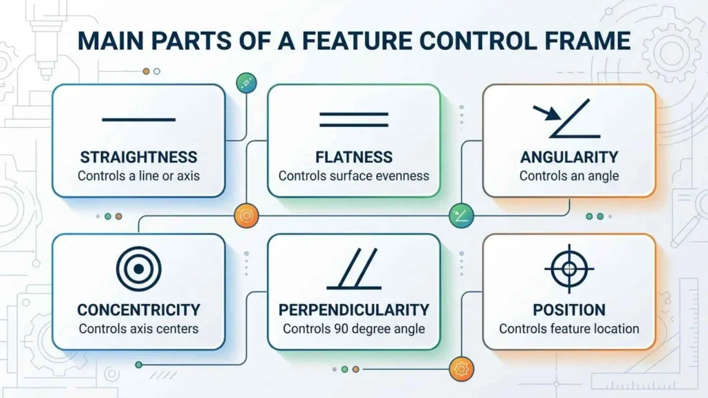
A typical feature control frame can contain:
- Geometric characteristic symbol: Identifies the control, such as position or flatness.
- Tolerance value: States the permitted geometric variation.
- Diameter symbol: Indicates a cylindrical tolerance zone where applicable.
- Material condition modifier: Specifies a permitted material-condition relationship where applicable.
- Datum references: Identify the reference features or datum system used by the control.
Not every feature control frame contains every element. A flatness callout, for example, doesn’t need datum references.
How to Read a Feature Control Frame
Consider this simplified example:
Position | ⌀0.20 | A | B | C
This notation represents a position tolerance with a cylindrical tolerance zone of 0.20, referenced to datums A, B, and C, assuming the drawing uses the corresponding standard conventions.
Here’s how to interpret its parts:
| Element | Interpretation |
| Position | Controls the specified feature’s location |
| ⌀0.20 | Specifies a cylindrical tolerance zone 0.20 units in diameter |
| A | Identifies the primary datum reference |
| B | Identifies the secondary datum reference |
| C | Identifies the tertiary datum reference |
The units, controlled feature, basic dimensions, modifiers, and datum definitions must also be checked before the requirement can be fully interpreted.
Common Feature Control Frame Mistakes
Watch for these frequent errors:
- Reading a diameter tolerance zone as a linear distance.
- Ignoring datum precedence.
- Confusing a basic dimension with a conventional ± tolerance.
- Applying a material condition modifier without understanding its effect.
- Assuming every geometric control requires datums.
- Interpreting a callout without checking drawing notes or the governing standard.
Understanding Datums and the Datum Reference System
A datum is a theoretically exact reference used to establish the coordinate framework for specifying and evaluating a part’s geometry. A physical datum feature is the actual part feature from which that reference is established.
Datums help manufacturers and inspectors evaluate geometric relationships consistently.
For example, a mounting plate might use its primary mounting face as datum A, a side surface as datum B, and an end surface as datum C. This arrangement can establish a repeatable reference system for locating holes.
Primary, Secondary, and Tertiary Datums
A datum reference frame commonly uses primary, secondary, and tertiary datum references. Their order establishes precedence under the applicable rules.
The primary datum establishes the first reference relationship. The secondary datum adds another constraint, and the tertiary datum can complete the locating scheme.
The familiar 3-2-1 locating concept helps illustrate how a rigid part can be constrained through contact points. However, actual datum establishment depends on the feature geometry, specified datum simulators, and governing standard.
Datum Symbols and Datum Feature Identification
Datum feature symbols identify the physical features used to establish datum references. Letters such as A, B, and C commonly appear in datum labels and feature control frames.
When reading a drawing, identify the actual feature associated with each datum letter. A letter alone doesn’t explain whether the datum comes from a plane, cylinder, hole, or another feature.
How to Select Functional Datums
Good datum selection reflects how the part functions and how it will be manufactured or inspected.
Consider these questions:
- Which surfaces locate the part during assembly?
- Which features establish its primary orientation?
- Which reference surfaces can manufacturing and inspection teams access reliably?
- Does the datum scheme represent the actual functional interface?
A poor datum scheme can create unnecessary inspection difficulty or fail to represent the way the part operates.
True Position in GD&T: Meaning and Applications
True Position describes the theoretically exact location of a feature relative to a specified reference system. Position tolerancing defines how much the actual feature may vary from that intended location.
It’s especially useful for mounting holes, dowel-pin holes, slots, and patterns that must align with other components.
How Position Tolerance Zones Work
Suppose a mounting plate has four holes. The drawing specifies their exact intended locations using basic dimensions and applies a position tolerance.
The tolerance zone defines the permitted location of each controlled feature relative to the datum reference frame.
When the callout specifies a cylindrical zone, the stated diameter describes the zone’s size. The measured feature must satisfy the applicable requirements for that zone and the feature’s size.
MMC, LMC, and Bonus Tolerance
Material condition modifiers affect how a geometric requirement relates to the size of a feature.
- Maximum Material Condition (MMC): The condition in which a feature of size contains the greatest amount of material within its applicable size limits. For an internal feature such as a hole, this generally occurs at the smallest permitted diameter.
- Least Material Condition (LMC): The condition in which a feature of size contains the least amount of material within its applicable size limits. For a hole, this generally occurs at the largest permitted diameter.
- Regardless of Material Boundary (RMB): An ASME term associated with datum reference requirements without a material-boundary modifier.
When a position tolerance uses MMC, the applicable rules can permit additional geometric tolerance as the feature departs from its maximum material condition. This additional allowance is called bonus tolerance.
For example, assume a hole has a 10.00 mm minimum diameter under the applicable size limits and a position tolerance of 0.20 mm at MMC. If its measured diameter is 10.10 mm, the difference from the MMC size is 0.10 mm. Under the assumed applicable MMC rules, that difference may provide 0.10 mm of bonus position tolerance.
This example illustrates the calculation only. Actual acceptance depends on the complete drawing specification and governing standard.
GD&T Standards: ASME Y14.5 and ISO GPS
Engineering teams must identify the governing standard before interpreting a GD&T drawing. Similar-looking callouts can have different rules or interpretations across standards.
What Is ASME Y14.5?
ASME Y14.5 establishes rules, definitions, symbols, requirements, and recommended practices for dimensioning and tolerancing.
It supports consistent communication of design intent on engineering drawings, digital product definitions, and related documentation.
As of October 2026, the ASME catalog identifies ASME Y14.5-2018 (R2024) as the reaffirmed edition currently in effect. See the official ASME Y14.5 listing. <sup>Source</sup>
What Is ISO GPS?
Geometrical Product Specifications (GPS) is an international standards framework for defining and verifying product geometry. It covers the principles and rules used to specify geometric requirements and evaluate manufactured workpieces.
Two important references are:
- ISO 1101:2017, which defines the symbol language and interpretation rules for geometrical tolerancing.
- ISO 8015:2011, which establishes fundamental concepts, principles, and rules for the GPS system.
ISO 1101:2017 was reviewed and confirmed in 2022, while ISO 8015:2011 was reviewed and confirmed in 2021, according to their official ISO listings. Check the relevant catalog before specifying a standard for a new project. <sup>ISO 1101 · ISO 8015</sup>
ASME Y14.5 vs. ISO GPS
| Comparison point | ASME Y14.5 | ISO GPS |
| Framework | A principal dimensioning and tolerancing standard | A broader family of product specification and verification standards |
| Common reference | Y14.5 | ISO 1101 and related GPS standards |
| Core purpose | Define and interpret dimensioning and tolerancing requirements | Define and interpret geometrical product specifications |
| Rules and terminology | Follow ASME conventions and definitions | Follow applicable ISO GPS principles and standards |
| Drawing interpretation | Requires the specified ASME edition and related notes | Requires the relevant ISO standards and specification rules |
Neither system should be treated as an automatic substitute for the other. Follow the standard stated in the drawing, contract, or customer specification.
Important GD&T Rules
Engineers should pay particular attention to the following:
- Follow the specified standard and edition.
- Check general tolerances and drawing notes.
- Understand the applicable size and geometric requirements.
- Interpret datum references in their specified order.
- Apply modifiers only where the governing rules permit them.
- Confirm how the drawing defines acceptance and verification.
Rule 1 is associated with ASME Y14.5 and concerns the relationship between size limits and permissible form variation for applicable features of size. Its detailed application depends on the standard’s provisions and exceptions. Avoid treating it as a universal rule for every surface or feature.
How to Read and Interpret a GD&T Drawing
Reading a GD&T drawing requires more than recognizing individual symbols. You must understand the complete specification and how its elements relate to one another.
Start With the Title Block and Drawing Notes
Before measuring a part, check:
- Units of measurement.
- Applicable dimensioning and tolerancing standard.
- General tolerances.
- Material and manufacturing requirements.
- Drawing revision and engineering change status.
- Special notes and inspection instructions.
These details can change how the drawing should be interpreted.
Identify Dimensions and Basic Dimensions
Basic dimensions define theoretically exact sizes, locations, or angles. They commonly work with geometric tolerances to establish intended geometry.
Don’t automatically apply a conventional ± tolerance to a basic dimension. Instead, find the geometric control that governs the feature’s permitted variation.
Read Geometric Callouts and Datums
For each relevant feature:
- Identify the feature the leader or callout controls.
- Read the geometric characteristic symbol.
- Check the tolerance value and any modifiers.
- Identify the datum references and their precedence.
- Connect the control to the relevant dimensions and drawing notes.
A callout’s meaning depends on its full context. Reading the symbol alone may leave important requirements unresolved.
Connect the Drawing to Inspection
The inspection method must evaluate the specified requirement. A caliper may verify a diameter, but it won’t necessarily establish whether a hole pattern meets its position tolerance.
Depending on the requirement, inspection may involve a coordinate measuring machine, suitable gauges, surface measurement equipment, or a defined functional fixture.
GD&T vs. Coordinate Dimensioning and Tolerancing
Coordinate dimensioning defines feature locations using dimensions from selected origins, edges, or reference points. GD&T can define geometric requirements and relationships that coordinate dimensions alone may not communicate fully.
These methods aren’t mutually exclusive. Most engineering drawings use dimensions alongside geometric controls as needed.
| Comparison point | Coordinate dimensioning | GD&T |
| Main purpose | Defines dimensions and coordinate-based locations | Defines dimensions and specified geometric requirements |
| Feature location | Uses stated coordinate dimensions and tolerances | Can use position or other suitable geometric controls |
| Form requirements | May need separate geometric specifications | Provides dedicated form controls |
| Functional relationships | Depends on the complete dimensioning scheme | Can communicate datum-based relationships directly |
| Inspection | Uses methods suited to the specified dimensions | Requires methods suited to the geometric controls |
| Cost impact | Depends on tolerance choices and inspection requirements | Can help avoid unnecessary restrictions when properly applied |
When Is Coordinate Tolerancing Enough?
Coordinate tolerancing can be sufficient when the part has simple dimensional requirements and its function doesn’t require additional geometric controls.
For example, a simple spacer may need only a length, width, thickness, and hole diameter. More complex components may need controls for flatness, perpendicularity, position, or profile.
When Should You Use GD&T?
GD&T becomes especially useful when geometric relationships affect assembly or performance.
Common examples include:
- Bolt-hole patterns that must align with mating parts.
- Bearing seats that depend on defined geometric relationships.
- Mounting surfaces that must maintain orientation.
- Rotating components that require runout control.
- Complex surfaces that need profile specifications.
The goal isn’t to replace every coordinate dimension. It’s to specify the geometry necessary for the part to function.
GD&T in Manufacturing, Quality Control, and Inspection
GD&T supports the complete manufacturing process, from initial design through final verification.
Manufacturing Applications
Manufacturing teams use GD&T when producing:
- CNC-machined components.
- Automotive mounting and drivetrain parts.
- Aerospace structures and precision components.
- Molded plastic housings.
- Cast and machined assemblies.
- Rotating shafts and bearing components.
Each application has different functional needs. A bolt-hole pattern may require position control, while a sealing face may need flatness or profile control.
Common GD&T Inspection Methods
| Inspection method | Typical application |
| Coordinate measuring machine (CMM) | Position, profile, orientation, and other suitable geometric evaluations |
| Surface plate and height gauge | Selected dimensional and geometric checks |
| Dial indicator | Runout and suitable comparative measurements |
| Optical or vision system | Selected feature locations, profiles, and dimensions |
| Functional gauge | Checking defined assembly or boundary requirements when properly specified |
| Surface measurement equipment | Evaluating suitable surface form and variation requirements |
The method must match the specification. A measurement system should also have suitable accuracy, calibration, setup, and uncertainty characteristics for the tolerance being evaluated.
Tolerance Verification and Part Acceptance
Inspection teams compare measured results with the specified requirements. They must consider the controlled feature, datum establishment, modifiers, measurement uncertainty, and applicable acceptance rules.
A part shouldn’t be rejected merely because one measurement looks unusual. Inspectors must determine whether the actual result violates the specified requirement using an appropriate evaluation method.
Clear specifications help reduce disagreements between manufacturers, suppliers, and customers.
Benefits of GD&T for Product Design and Manufacturing
When engineers apply GD&T correctly, it can improve communication and make geometric requirements easier to verify.
Key benefits include:
- Clearer engineering communication: Designers, machinists, and inspectors use standardized symbols and definitions.
- Improved assembly: Suitable geometric controls help mating features align and function.
- Better tolerance allocation: Engineers can distinguish critical characteristics from less important ones.
- More consistent inspection: Defined controls support repeatable evaluation.
- Manufacturing efficiency: Appropriate tolerances can help avoid unnecessary machining and inspection work.
- Improved quality assurance: Clear requirements provide a stronger basis for acceptance decisions.
These outcomes depend on the quality of the design specification. GD&T can’t compensate for a poorly chosen datum system or a tolerance that doesn’t reflect the part’s actual function.
Practical GD&T Examples: Applying Geometric Controls to Real Parts
Real-world examples make the difference between dimensions and geometric controls easier to understand.
Example: Flatness of a Mirror or Mounting Surface
Imagine a mirror that requires a highly controlled reflective surface. Its thickness may meet the drawing’s dimensional limits, yet the surface can still have unwanted shape variation.
Thickness and flatness describe different requirements. A thickness tolerance controls the distance between specified surfaces or boundaries, as defined by the drawing. A flatness tolerance controls the form of the specified surface.
For a mounting plate, flatness may help ensure reliable contact. For a mirror, surface shape can affect optical performance, but the required optical specification may extend beyond ordinary mechanical flatness.
The designer must choose a control that matches the actual functional need.
Example: Position of Bolt Holes on a Mounting Plate
A plate has four holes that must align with a mating component. The drawing establishes the plate’s mounting surface and other locating features as datums.
The engineer specifies the hole locations using basic dimensions and applies a position tolerance relative to the datum reference frame.
During inspection, the team evaluates whether the hole features meet the specified position requirement. This approach controls the hole pattern’s functional relationship rather than checking only the distance between individual holes.
Example: Perpendicularity of a Machined Face
A bracket has a base surface and a vertical mounting face. The vertical face must maintain a specified perpendicular relationship to the base.
The designer establishes the appropriate datum and applies a perpendicularity tolerance. Manufacturing can then choose a suitable machining setup, while inspection evaluates the specified orientation.
This requirement helps control the angular relationship that matters to assembly.
Example: Runout of a Rotating Shaft
A rotating shaft may need to run accurately relative to its bearing axis. The drawing establishes a datum axis and applies an appropriate runout control.
Circular runout evaluates variation at individual circular elements during rotation. Total runout evaluates variation over the full specified surface.
The inspection setup must establish the datum axis correctly. Otherwise, the measurement may not reflect the intended geometric requirement.
Example: Straightness of a Shaft
A shaft may satisfy its diameter limits but still have a geometric shape that affects its operation.
A suitable straightness control can limit variation in the specified line element or applicable derived feature. The exact callout matters because surface straightness and axis straightness aren’t interchangeable requirements.
The designer should select the control based on how the shaft functions and how its geometry needs to be evaluated.
Common GD&T Mistakes and How to Avoid Them
Even experienced teams can misinterpret a drawing when they overlook a detail.
Applying Unnecessarily Tight Tolerances
A tolerance should reflect functional needs and manufacturing capability. Tightening every tolerance can raise costs without improving the final product.
Better approach: Identify critical interfaces first, then assign tolerances based on function and process capability.
Choosing Poor Datum References
Datums that don’t reflect assembly conditions can make inspection difficult or produce misleading evaluations.
Better approach: Select datum features that represent the part’s functional location and orientation.
Confusing Size and Geometric Tolerances
A part can meet its size requirements yet violate a geometric control.
Better approach: Evaluate size and geometry separately wherever the drawing specifies both.
Mixing ASME and ISO GPS Rules
Similar symbols don’t guarantee identical interpretation rules.
Better approach: Confirm the governing standard and edition before applying acceptance criteria.
Ignoring Inspection Capability
A requirement may be difficult to verify with the available equipment or measurement setup.
Better approach: Involve manufacturing and quality teams during design so they can assess feasibility before production begins.
How to Learn GD&T: Training and Practical Skills
Learning GD&T is easier when you build your knowledge in stages.
Start With the Fundamentals
Begin with engineering drawings, dimensional tolerances, geometric characteristic symbols, datum references, and feature control frames.
Next, study how the controls relate to real components. Understanding why a hole pattern needs position control is more useful than memorizing a symbol without context.
Practice With Real Drawings
Choose simple parts and work through their requirements.
- Identify the nominal dimensions and size limits.
- Find the datum features.
- Interpret each feature control frame.
- Determine the required geometric tolerance.
- Consider an appropriate inspection method.
- Explain why the control matters to function.
Practice with several part types, including shafts, brackets, mounting plates, and housings.
Choose Relevant GD&T Training
Training should match your role. Designers may need to focus on specification and tolerance allocation, while inspectors may need deeper practice with datum establishment and measurement.
ASME provides GD&T training and related resources. Its catalog also lists certification requirements for GD&T professionals.
A structured course can provide a useful foundation, but regular drawing interpretation and practical application build lasting skill.
Frequently Asked Questions About GD&T
What Does GD&T Stand For?
GD&T stands for Geometric Dimensioning and Tolerancing. It is a standardized system for specifying allowable variation in the geometry of manufactured parts.
What Is GD&T Used For?
Engineers use GD&T to define and communicate geometric requirements on engineering drawings and digital product definitions. It supports manufacturing, assembly, inspection, and quality assurance.
What Are the Basic GD&T Symbols?
Common symbols identify straightness, flatness, circularity, cylindricity, parallelism, perpendicularity, angularity, position, profile, and runout controls. The applicable standard defines their exact meaning.
What Are the Four Components of SLOF?
SLOF stands for Size, Location, Orientation, and Form. It is a helpful learning framework for organizing fundamental geometric requirements, although it doesn’t cover every GD&T control by itself.
What Is a Feature Control Frame?
A feature control frame is a rectangular callout that specifies a geometric characteristic and its tolerance. It may also include datum references and permitted modifiers.
What Is the Purpose of a Datum in GD&T?
A datum establishes a theoretically exact reference for specifying and evaluating geometry. Datum references help define the coordinate framework used to control a feature’s location or orientation.
What Is True Position in GD&T?
True Position refers to the theoretically exact location of a feature. A position tolerance defines the permitted variation around that intended location relative to the specified reference system.
What Is the Difference Between ASME Y14.5 and ISO GPS?
ASME Y14.5 is a principal dimensioning and tolerancing standard, while ISO GPS is a broader family of standards for geometrical product specification and verification. Their rules and terminology aren’t fully interchangeable.
Does GD&T Replace Plus-Minus Tolerancing?
No. GD&T complements conventional dimensional tolerancing. Drawings commonly use size dimensions, plus-minus tolerances, basic dimensions, and geometric controls together.
How Does GD&T Help Reduce Manufacturing Costs?
GD&T can reduce unnecessary restrictions by connecting tolerances to functional requirements. When applied correctly, it may lower rework, scrap, and inspection costs while improving assembly consistency.
Which GD&T Standard Should an Engineer Follow?
Follow the standard and edition identified in the drawing, contract, or customer specification. If the governing requirements aren’t clear, resolve the ambiguity before manufacturing or accepting the part.
Conclusion: Using GD&T to Communicate Design Intent
Geometric Dimensioning and Tolerancing gives engineers a consistent way to describe acceptable variation in manufactured parts. It connects dimensions with geometric requirements so teams can understand how features must fit, align, and function.
The most important concepts include GD&T symbols, datum reference systems, feature control frames, tolerance zones, and applicable standards. Each plays a role in defining and verifying a component’s geometry.
To use GD&T effectively, start with the part’s functional requirements. Choose suitable datums, apply meaningful controls, and make sure manufacturing and inspection teams can interpret the drawing consistently.
When the specification reflects the product’s real needs, GD&T becomes more than a set of symbols. It becomes a practical tool for improving communication, controlling variation, and producing reliable components.

I am John Carter, a lifelong enthusiast of language and modern slang. I explore how words evolve and shape culture, and I enjoy uncovering the stories behind everyday expressions. I have authored “Slang and Society: The Language of Youth” and “Modern Words, Modern Worlds”, where I dive into how informal language impacts communication and identity. My goal is to make language accessible, fun, and insightful for everyone who loves words as much as I do.
 Lisa Reynolds