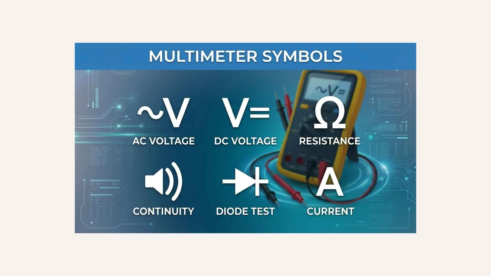
A multimeter can measure voltage, current, resistance, and several other electrical properties. However, before you can use one confidently, you need to understand its multimeter symbols. The icons on the dial, buttons, input jacks, and display tell you which function to select and how to interpret your readings.
Some symbols are easy to recognize. The Greek letter omega (), for example, represents resistance. Other markings can be confusing, especially the straight and wavy lines used for DC and AC measurements. Symbols such as OL, HOLD, Hz, and the diode icon also have specific meanings that affect how you test electrical circuits.
This guide explains common digital multimeter symbols, advanced measurement functions, units, range markings, display indicators, and input terminals. You’ll also learn how to use these functions for everyday electrical checks and PCB troubleshooting, along with essential safety precautions.
Quick Answer: What Do Multimeter Symbols Mean?
Multimeter symbols identify the electrical quantity a meter measures and the mode it uses. V⎓ generally means DC voltage, V~ means AC voltage, Ω means resistance, and a sound-wave or speaker icon often indicates continuity testing. A represents current, Hz represents frequency, and a diode icon identifies diode-test mode. Exact symbols and available functions vary by meter model, so always check the manufacturer’s manual.
What Do Multimeter Symbols Mean?
A multimeter symbol is a marking that identifies a measurement function, setting, unit, or control. Selecting the correct symbol helps you take a useful reading and avoid damaging the meter or the circuit.
Most digital multimeters have several groups of symbols:
- Measurement symbols: Identify functions such as voltage, current, resistance, capacitance, and frequency.
- AC and DC symbols: Show whether a measurement is intended for alternating current or direct current.
- Range markings: Indicate measurement ranges or limits on meters with manual ranging.
- Input-jack labels: Tell you where to connect the black and red test leads.
- Display indicators: Show units, negative readings, low battery, hold status, or an out-of-range result.
- Control symbols: Identify buttons such as HOLD, RANGE, SELECT, and backlight.
These markings work together. For example, choosing the DC voltage function and connecting the probes to the correct terminals allows you to measure the voltage across a battery.
A symbol alone doesn’t tell you every detail about a measurement. You must also consider the selected range, input terminals, meter ratings, and the circuit you’re testing.
Where Are Multimeter Symbols Located?
You’ll usually find symbols in four places:
- Rotary dial: Selects the main measurement function.
- Buttons: Activate secondary functions or change settings.
- Input jacks: Identify where each test lead belongs.
- Digital display: Shows the reading and supporting indicators.
On some meters, one dial position supports multiple functions. A SELECT or MODE button switches between them. Other meters use separate dial positions for each function.
The same measurement may also have different markings on different brands. Use the symbol guide as a general reference, then confirm unfamiliar functions in your meter’s manual.
Multimeter Symbols Chart: Common Icons and Their Meanings
Use this multimeter symbols chart to identify common dial markings and understand when to use them. The icons shown below are standard representations, but the exact design can vary by manufacturer.
| Multimeter symbol | Meaning | Common use |
| V⎓ | DC voltage | Testing batteries, power supplies, and DC circuits |
| V~ | AC voltage | Measuring AC voltage in suitable circuits |
| mV | Millivolts | Measuring small voltage signals |
| A⎓ | DC current | Measuring current flowing in a DC circuit |
| A~ | AC current | Measuring alternating current |
| Ω | Resistance | Checking resistors and resistance in unpowered circuits |
| Sound-wave or speaker icon | Continuity | Checking whether two points have a low-resistance connection |
| Diode icon | Diode test | Checking a diode’s forward voltage drop |
| F or capacitor icon | Capacitance | Measuring capacitor capacitance |
| Hz | Frequency | Measuring cycles per second |
| % | Duty cycle | Measuring the percentage of time a signal stays active |
| °C / °F | Temperature | Measuring temperature with a compatible sensor |
| hFE | Transistor DC current gain | Testing certain bipolar transistors |
| HOLD | Display hold | Freezing a reading on the screen |
| ☀ or light icon | Backlight | Lighting the display on supported models |
| OFF | Power off | Switching off the meter |
| COM | Common terminal | Connecting the black test lead |
| mA / μA | Milliamp / microamp input | Measuring smaller currents through the correct jack |
| A or 10A | Current input | Measuring current within the jack’s rated limits |
| VΩ | Voltage and resistance input | Connecting the red lead for voltage, resistance, and other supported functions |
Important: A symbol’s presence doesn’t mean every meter supports that function. Some meters combine several functions into one dial position, while others use separate positions or buttons. Fluke’s digital multimeter dial and display guide provides examples of how these layouts differ by model.
Fluke
Basic Multimeter Dial Symbols Explained
Understanding the main dial symbols is the first step toward taking reliable measurements. Start with voltage, current, resistance, continuity, and diode testing before moving to advanced features.
DC Voltage Symbol (V⎓)
Symbol: V with a solid line above a dashed line
The DC voltage symbol identifies the setting used to measure direct-current voltage. DC voltage has a fixed polarity: one point is positive relative to another, although the measured value can be negative if the probes are reversed.
Common applications include:
- Testing AA, AAA, and rechargeable batteries.
- Checking a USB power supply or DC adapter.
- Measuring a circuit’s 3.3 V or 5 V power rail.
- Checking the output of a DC regulator.
- Troubleshooting small electronic devices.
How to use it: Place the black lead in COM and the red lead in the voltage input. Select V⎓, then touch the probes across the two points you want to compare.
Voltage is measured in parallel with the component or circuit section. For example, when checking a battery, place one probe on each terminal. Don’t put the meter in current mode and connect it directly across the battery.
AC Voltage Symbol (V~)
Symbol: V with a wavy line
The AC voltage symbol indicates alternating-current voltage measurement. AC voltage changes over time and reverses polarity periodically in common power systems.
You may use this setting to test:
- AC output from a suitable transformer.
- Voltage in an AC-powered circuit.
- Mains voltage, but only with a properly rated meter, probes, and appropriate training.
- AC signals from compatible equipment.
The wavy line (~) is the key clue that the measurement involves alternating current or voltage. Some meters use a wavy line beside V, while others print AC or combine AC and DC functions.
Never assume that a meter is safe for mains testing just because it has a V~ setting. Check the meter’s maximum voltage, measurement-category rating, probe rating, and manufacturer’s instructions. Mains electricity can cause serious injury or death.
DC Current Symbol (A⎓)
The DC current symbol identifies a function for measuring direct current. Current is the rate at which electric charge flows through a circuit, and its unit is the ampere (A).
Typical applications include checking the current drawn by a small electronic circuit, battery-powered device, or DC component.
Unlike voltage, current measurement usually requires the meter to become part of the current path. You generally need to:
- Turn off power before changing the circuit connection.
- Move the red lead to the correct current input if required.
- Select the appropriate DC current range.
- Open the circuit and connect the meter in series.
- Confirm that the expected current is within the meter’s rating.
Never connect a meter in current mode directly across a battery or voltage source. The meter’s low-resistance current path can create a short circuit and may blow a fuse, damage equipment, or cause injury.
AC Current Symbol (A~)
The AC current symbol indicates measurement of alternating current. It appears on meters that support AC current measurement through test leads or an appropriate current clamp.
Some digital multimeters measure current only up to a specified limit. Others offer a separate milliamp input or microamp range for smaller signals.
Before measuring current, check:
- Whether the meter supports AC current.
- The current rating of the selected input.
- Whether the input is fused.
- Whether the test leads are in the correct jacks.
- Whether a clamp accessory is required for the measurement.
A current clamp can measure current by surrounding a conductor, where supported. This can avoid opening the circuit, but the clamp must be suitable for the type and magnitude of current being measured.
Resistance Symbol (Ω)
The Greek letter omega (Ω) represents electrical resistance, measured in ohms. Resistance describes how strongly a component opposes current flow.
Use the resistance setting to check:
- Resistors.
- Some wires and connectors.
- Switch contacts.
- Certain coils and windings.
- Circuit paths when the circuit is unpowered.
A low resistance reading may indicate a good connection, but context matters. A resistor designed for 100 Ω should not normally measure 10 kΩ. A wire may measure close to zero ohms, while a high-value resistor should show a much larger value.
Always turn off circuit power before measuring resistance. Discharge capacitors safely and follow the device’s service instructions. Voltage present in the circuit can produce false readings and may damage the meter.
Also remember that in-circuit readings can be affected by other components connected in parallel. If a resistor’s reading doesn’t match its marked value, you may need to isolate one lead before testing it.
Continuity Symbol: Beep or Sound Waves
The continuity symbol often resembles a speaker, sound waves, or a diode combined with a sound icon. Continuity mode checks whether an electrical path has sufficiently low resistance for the meter’s built-in threshold.
When the path meets that threshold, many meters produce a beep. This makes continuity testing useful when you want to check a wire or connection without watching the display constantly.
Common uses include:
- Checking a fuse after removing it from the circuit.
- Testing a wire for a break.
- Checking a switch’s contacts.
- Finding an open trace on a printed circuit board.
- Checking connectors and solder joints.
A beep doesn’t automatically prove that a connection is perfect. The meter’s threshold varies, and a partially damaged connection may still beep. For a more complete assessment, measure resistance and compare the reading with the expected value.
Never use continuity mode on an energized circuit. Disconnect power and verify the circuit is safe before testing.
Diode Test Symbol
The diode symbol marks a function that applies a small test current and displays the diode’s forward voltage drop. The exact symbol may look like a triangle-like arrow shape pointing toward a vertical line, depending on how it is printed.
This mode can help you check ordinary diodes, some LEDs, and semiconductor junctions.
A typical test involves:
- Disconnecting circuit power.
- Identifying the diode’s anode and cathode.
- Selecting diode-test mode.
- Placing the probes across the diode.
- Reading the displayed forward voltage.
A healthy silicon diode often shows a forward drop around 0.5–0.8 V under a suitable test current. This is a typical range, not a universal pass/fail rule. Schottky diodes, LEDs, germanium devices, and other components can show different values.
Reversing the probes on a functioning diode often produces an out-of-range indication. However, readings taken while a component remains connected to a circuit can be affected by other paths. Check the component datasheet and meter manual when a result seems unusual.
Advanced Multimeter Symbols and Functions
Many modern digital multimeters include extra settings for electronic components, signal measurements, and temperature checks. These features can save time, but their availability depends on the meter.
Capacitance Symbol (F)
The capacitance symbol may appear as F or as a small capacitor icon. Capacitance measures a capacitor’s ability to store electrical charge, and the unit is the farad (F).
Common applications include checking capacitors in electronic circuits, power supplies, and selected appliances.
Capacitance readings may be shown in:
- pF: picofarads
- nF: nanofarads
- μF: microfarads
- mF: millifarads
Before measuring capacitance, disconnect power and discharge the capacitor using a suitable method. Large capacitors can retain a dangerous charge after equipment is switched off. Follow the manufacturer’s instructions and never short a capacitor with a screwdriver as a general discharge method.
In-circuit capacitance measurements may be inaccurate because other components can affect the reading. For a reliable comparison, isolate the capacitor when the service procedure allows it.
Frequency Symbol (Hz)
The Hz symbol stands for hertz, the unit of frequency. One hertz equals one cycle per second.
Frequency measurement helps assess repetitive electrical signals, such as compatible AC signals or electronic waveforms. For example, a 50 Hz signal completes 50 cycles per second.
Meters vary in the frequency range they can measure and in the signal amplitude or waveform they require. Some models can measure frequency only through certain input terminals or measurement modes.
Don’t assume that a meter can safely measure every signal that falls within its displayed frequency range. Confirm the voltage limits and input requirements first.
Duty Cycle Symbol (%)
The duty cycle symbol is usually a percent sign (%), sometimes available as a secondary function. Duty cycle describes the percentage of each repeating cycle that a signal remains in its active state.
For example, a 25% duty cycle means the signal is active for one-quarter of each cycle under the measurement’s defined convention.
Duty-cycle measurements can help when examining pulse-width-modulated signals, control circuits, and some electronic systems. Not all meters can measure duty cycle, and some require you to press SELECT or MODE while using the frequency function.
Temperature Symbols (°C and °F)
Temperature settings are marked °C for degrees Celsius and °F for degrees Fahrenheit. A compatible meter may use a thermocouple probe to measure temperature.
This function can help with:
- Checking component or enclosure temperature.
- Comparing temperatures before and after a repair.
- Monitoring selected motors or power supplies.
- Troubleshooting overheating in suitable equipment.
Use only a compatible sensor and the meter’s specified input. A temperature function does not make the meter suitable for measuring every hot surface or industrial process.
Transistor Gain Symbol (hFE)
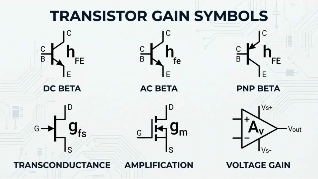
The hFE symbol refers to the DC current gain of certain bipolar junction transistors. Some meters include a socket for inserting a transistor’s leads.
This feature is useful for a quick, basic transistor check. However, the result depends on the test conditions and does not fully establish whether a transistor will work correctly in a real circuit.
For accurate component evaluation, consult the transistor datasheet and use suitable test equipment. Many modern meters don’t include an hFE function.
Combined Functions and Secondary Symbols
Some meters place more than one symbol around a dial position. A button labeled SELECT, MODE, or a colored secondary marking may switch between functions.
For example, a single dial position might support resistance, continuity, and diode testing. Another may combine AC and DC current measurement.
Before taking a measurement:
- Read the symbols around the dial carefully.
- Check whether a button changes the selected function.
- Confirm the active mode on the display.
- Consult the manual if the symbol or button behavior isn’t clear.
Never guess the active mode based only on the dial position.
Multimeter Units, Abbreviations, and Prefixes
Understanding the letters and prefixes beside a reading is just as important as understanding the dial icons. A reading of 2.0 mV is very different from 2.0 V, even though the displayed number looks similar.
Common Multimeter Units
| Symbol | Unit | What it measures |
| V | Volt | Voltage |
| A | Ampere | Electric current |
| Ω | Ohm | Resistance |
| F | Farad | Capacitance |
| Hz | Hertz | Frequency |
| °C | Degrees Celsius | Temperature |
| °F | Degrees Fahrenheit | Temperature |
| W | Watt | Electrical power, where supported |
| % | Percent | Duty cycle or another percentage-based function |
Not every multimeter measures every quantity in this table. Watts, for example, aren’t a standard standalone function on all handheld meters.
Metric Prefixes on a Multimeter Display
Metric prefixes show how large or small a measurement is relative to its base unit.
| Prefix | Symbol | Multiplier | Example |
| Giga | G | 109 | 1 GΩ = 1,000,000,000 Ω |
| Mega | M | 106 | 1 MΩ = 1,000,000 Ω |
| Kilo | k | 103 | 1 kΩ = 1,000 Ω |
| Milli | m | 10-3 | 1 mA = 0.001 A |
| Micro | μ | 10-6 | 1 μA = 0.000001 A |
| Nano | n | 10-9 | 1 nF = 0.000000001 F |
| Pico | p | 10-12 | 1 pF = 0.000000000001 F |
Pay special attention to letter case. M usually means mega, while m means milli. Confusing them can lead to a million-fold error in interpreting a measurement.
What Do 200m, 2000m, 2V, and 20V Mean?
These markings often appear on meters with manual range selection. They indicate the measurement range associated with the selected function.
For voltage measurement, examples may include:
- 200 mV: A range up to around 200 millivolts.
- 2000 mV: A range up to around 2000 millivolts, equal to 2 volts.
- 2 V: A range up to around 2 volts.
- 20 V: A range up to around 20 volts.
The exact display and maximum usable value depend on the meter’s design. The markings may also differ when measuring resistance or current, so don’t interpret a number without checking the active function.
A meter with auto-ranging selects an appropriate range automatically. A manual-ranging meter requires you to choose one. If the reading exceeds the selected range, the display may show OL or another overload indication.
What Does OL Mean on a Multimeter?
OL commonly means over limit, overload, or an out-of-range reading. Its precise meaning depends on the meter and selected function.
For example:
- In resistance mode, OL may mean resistance is above the selected range or the circuit path is open.
- In voltage mode, OL may mean the measured value exceeds the selected range or the meter’s display limit.
- In continuity mode, OL often indicates that the measured path doesn’t meet the continuity threshold.
Don’t treat OL as proof that a component is faulty. First check the selected mode, range, connections, and meter manual. On some meters, a displayed “1” at the far left serves as an over-range indicator rather than the letters OL.
Understanding the Multimeter Dial, Buttons, and Input Jacks
The rotary dial selects a measurement function, but the buttons, terminals, and display also affect the result. Learning these parts helps you avoid common mistakes.
Rotary Dial and Range Selector
The rotary dial is the main control on most digital multimeters. It lets you select voltage, current, resistance, continuity, diode testing, or other supported functions.
Meters generally use one of two range-selection systems:
- Manual ranging: You choose the range yourself, such as 2 V or 20 V.
- Auto-ranging: The meter selects a suitable range based on the measured value.
Manual ranging gives you more direct control, but you need to select a range that can accommodate the expected reading. Auto-ranging is convenient for beginners, although the display may take a moment to settle.
If you’re unsure of the expected value, begin with a suitable higher range when using a manual-ranging meter. Never exceed the meter’s stated voltage, current, or input limits.
COM, VΩmA, and 10A Input Jacks
Input jacks are the sockets where you connect the test leads. The correct socket depends on the measurement.
| Input marking | Typical purpose | Important note |
| COM | Black lead for most measurements | Usually the common or return connection |
| VΩ or VΩHz | Voltage, resistance, and supported secondary functions | Common red-lead input for voltage testing |
| mA / μA | Low-current measurements | Observe the jack’s current and time limits |
| A / 10A | Higher-current measurements within the stated rating | Use only for current measurements supported by that input |
Some meters combine the mA and μA input with other functions. Others provide separate sockets. Always follow the labels on your specific meter.
Safety reminder: Never leave the red lead in a current jack and then attempt a voltage measurement. The wrong connection can create a short circuit when the probes touch a voltage source.
Fluke+1
HOLD, BACKLIGHT, SELECT, RANGE, and REL Buttons
Buttons often control features that don’t have a dedicated rotary-dial position.
- HOLD: Freezes the displayed measurement so you can read or record it.
- Backlight: Illuminates the display in dim conditions.
- SELECT / MODE: Switches between functions sharing a dial position.
- RANGE: Changes the measurement range on compatible meters.
- REL / ZERO: Sets a relative reference so you can compare changes against a baseline.
- MIN/MAX: Records minimum and maximum values during a measurement on supported models.
These features are helpful, but they can also confuse readings if you forget they’re active. For instance, HOLD may leave an older value on the display even after you move the probes.
If a reading doesn’t change as expected, check the display for an active hold, relative mode, or other indicator before assuming the circuit is faulty.
Understanding Multimeter Display Symbols
The display communicates more than the measured number. It may also show the selected function, unit, polarity, range, and warnings.
| Display indicator | Typical meaning | What to check |
| Minus sign (−) | Negative reading or reversed polarity relative to the probes | Check probe placement and expected polarity |
| Low-battery icon | Battery needs attention | Replace it according to the manual |
| HOLD | Reading is frozen | Disable hold to see live measurements |
| AUTO | Auto-ranging is active | The meter is selecting a range |
| OL | Over-range or open-circuit indication, depending on mode | Check range, connections, and function |
| Ω | Resistance measurement or unit | Confirm the meter is in the intended mode |
| V, A, mA, μA | Voltage or current unit | Check the scale and active function |
| Hz | Frequency measurement | Confirm the signal and input are within limits |
A negative DC voltage reading doesn’t automatically mean the circuit is defective. If you measure a battery with the probes reversed, the meter may show the correct magnitude with a minus sign.
How to Use Multimeter Symbols for Electrical Measurements
Correctly identifying a symbol is only the first step. You also need to connect the probes properly and follow the right procedure for each measurement.
How to Measure DC Voltage
Use this procedure to check a battery or a low-voltage DC circuit:
- Inspect the meter and test leads for damage.
- Connect the black lead to COM and the red lead to the voltage input.
- Select V⎓.
- Choose a suitable range if the meter isn’t auto-ranging.
- Place the probes across the two points being measured.
- Read the voltage and check the unit shown on the display.
For example, a nominal 1.5 V alkaline battery may show a reading near 1.5 V when new, although the actual result depends on its condition and load. A reading alone doesn’t fully determine battery health.
How to Measure AC Voltage
AC voltage measurements require extra care because some sources can be hazardous.
- Confirm that the meter and probes are rated for the circuit.
- Keep the black lead in COM and the red lead in the voltage jack.
- Select V~ or the appropriate AC voltage function.
- Use the probes only as described in the manufacturer’s instructions.
- Compare the result with the expected voltage for the equipment.
Do not use an unrated or damaged meter to test mains electricity. If you lack electrical training, ask a qualified professional to perform hazardous voltage measurements.
How to Measure Current
Current measurements require the meter to be connected in series unless you’re using a suitable current clamp.
- Switch off power before changing the circuit connections.
- Move the red lead to the correct current jack.
- Select A⎓, A~, mA, or μA as appropriate.
- Confirm the expected current is within the meter’s input rating.
- Connect the meter in series with the circuit.
- Restore power only when the connections are secure and the procedure is safe.
- Turn off power before removing the meter and restoring the circuit.
Never place a current-configured multimeter directly across a battery, outlet, or power supply. That can create a dangerous short circuit.
How to Measure Resistance
Resistance testing is useful for checking resistors, wires, and selected components.
- Turn off power to the circuit.
- Verify that the circuit is de-energized.
- Discharge capacitors using an appropriate procedure.
- Place the black lead in COM and the red lead in the correct input.
- Select Ω.
- Touch the probes across the component or circuit path.
- Compare the reading with the expected value.
Remember that nearby components can create alternate paths. If an in-circuit resistance reading seems incorrect, consult the circuit diagram and service procedure to determine whether one component lead should be isolated.
How to Test Continuity and Diodes
For continuity testing, select the sound-wave or continuity icon and connect the probes across the unpowered path. A beep usually means the resistance is below the meter’s continuity threshold.
For diode testing, select the diode icon and connect the probes across the component. A forward-voltage reading can help indicate whether the junction behaves as expected.
Both tests require a safe, unpowered circuit. A beep or a single diode reading doesn’t prove that a component will perform correctly under normal operating conditions.
How to Measure Capacitance, Frequency, and Temperature
Advanced measurements depend on your meter’s supported features and the correct accessories.
- Capacitance: Select F or the capacitor icon. Discharge the capacitor safely before testing.
- Frequency: Select Hz or the supported frequency function. Confirm that the signal’s voltage and frequency are within the meter’s limits.
- Temperature: Select °C or °F and use the specified temperature probe.
- Duty cycle: Select the percent or duty-cycle function, if available, and connect to the signal as directed by the manual.
Check the manual whenever the function uses a secondary button or an unfamiliar input jack.
How to Use Multimeter Symbols for PCB Testing and Troubleshooting
A digital multimeter is a useful tool for printed circuit board (PCB) troubleshooting. It can help you identify missing supply voltage, open connections, suspicious resistance readings, and certain component faults.
However, no single multimeter reading can diagnose every PCB problem. Use the schematic, board documentation, component datasheets, and expected operating values to interpret the results.
Check PCB Power Rails Using DC Voltage
Electronic boards often contain power rails such as 3.3 V or 5 V, but these values aren’t universal. Check the board’s schematic or technical documentation before measuring.
To check a power rail:
- Select V⎓.
- Connect the black probe to the documented ground point.
- Touch the red probe to the test point for the rail.
- Compare the reading with the expected voltage.
- Check whether the voltage remains stable under the intended operating conditions, where safe.
An incorrect reading may point to a supply problem, a short, a faulty regulator, or a measurement error. It doesn’t identify the root cause on its own.
Avoid slipping probe tips between closely spaced pins. A brief short between adjacent pins can damage a board.
Check for a PCB Short Circuit
Continuity mode can help you investigate a suspected short, but a low-resistance reading doesn’t always mean something is wrong. Some power rails naturally have low resistance to ground because of the components connected to them.
A careful check involves:
- Disconnecting the board from its power source.
- Following the manufacturer’s instructions for stored-energy discharge.
- Selecting continuity or resistance mode.
- Measuring between the suspected power rail and ground.
- Comparing the result with the board’s expected behavior or a known-good board.
A continuous beep may indicate a short, but it may also reflect normal circuit design. Consider the schematic, component values, and the meter’s resistance reading before deciding.
Test PCB Traces, Connectors, and Solder Joints
Use continuity mode to check whether an unpowered trace or connection provides an electrical path.
This can help identify:
- Broken PCB traces.
- Loose connectors.
- Open wires.
- Poor solder joints.
- Damaged switches.
- Certain open fuses.
A good connection usually shows low resistance, although the expected value depends on the path and measurement setup. A solder joint can also pass a simple continuity test while failing under mechanical stress or load, so inspect the board and use other diagnostic methods when necessary.
Test Resistors, Diodes, LEDs, and Capacitors on a PCB
Multimeter functions can help assess several common components:
| Component | Useful multimeter function | What the result can tell you |
| Resistor | Ω | Whether the measured resistance is broadly consistent with its expected value |
| Diode | Diode test | Whether the junction shows a plausible forward drop |
| LED | Diode test | Whether the LED junction conducts under the meter’s test conditions; some LEDs may not visibly light |
| Capacitor | Capacitance (F) | Whether measured capacitance is close to its rated value |
| Fuse | Continuity or Ω | Whether the fuse appears open or has a low-resistance path |
In-circuit readings may differ from expected values because other components affect the measurement. When necessary, follow the service instructions to isolate the component before testing it.
Check a Voltage Regulator’s Output
A voltage regulator supplies a controlled voltage to part of a circuit. To investigate its output, identify the input, ground, and output pins using the schematic or component datasheet.
Then, if the measurement can be performed safely:
- Select DC voltage mode.
- Connect the probes to the documented reference and output points.
- Compare the reading with the regulator’s specified output.
- Check the input supply if the output is incorrect.
- Inspect for overheating or visible damage when the board is unpowered.
Don’t guess pin locations based on the package shape. Similar-looking components may use different pinouts, and probe slips can short adjacent pins.
Common Multimeter Symbol Mistakes and How to Fix Them
Even experienced users can misread a display or choose the wrong function. These are some of the most common mistakes and the steps that help prevent them.
| Common mistake | Why it causes problems | How to avoid it |
| Choosing AC instead of DC | The reading may be incorrect or misleading | Match the mode to the type of signal |
| Choosing voltage instead of current | The meter won’t measure the intended quantity | Confirm the dial setting before connecting |
| Leaving the red lead in the current jack | Voltage testing can create a short circuit | Check the input jack before every measurement |
| Measuring resistance on a powered circuit | Readings may be wrong and the meter may be damaged | Disconnect power and discharge capacitors safely |
| Treating every beep as proof of a good connection | Continuity mode has a resistance threshold | Check resistance and inspect the connection |
| Assuming OL always means a broken wire | OL can indicate over-range or an open path | Check the active function and manual |
| Selecting a range that’s too low | The reading may exceed the selected range | Select an appropriate range or use auto-ranging |
| Ignoring a low-battery indicator | The meter may behave unreliably | Replace the battery as instructed |
| Assuming a low resistance means a PCB short | Some normal circuits have low resistance to ground | Compare the reading with the circuit design |
| Ignoring the unit prefix | mV, V, mA, and A represent different scales | Read the complete number and unit together |
A simple habit prevents many of these errors: check the function, input jack, range, and display before taking a measurement.
Electrical Safety Rules When Using a Multimeter
Understanding multimeter symbols is essential, but correct technique and suitable equipment are just as important. A multimeter can expose you to electrical hazards if you use it incorrectly.
Follow these precautions:
- Inspect the meter and leads. Don’t use equipment with cracked cases, damaged insulation, loose connectors, or exposed metal.
- Check the ratings. The meter and probes must be suitable for the voltage, current, and electrical environment.
- Use the correct input jack. Voltage and resistance measurements typically use a different red-lead input from current measurements.
- Never measure resistance on a live circuit. Disconnect power and follow the correct procedure for discharging stored energy.
- Use current mode carefully. The meter usually needs to be connected in series. Never connect it directly across a voltage source while configured to measure current.
- Respect current limits. Check the input rating, fuse, measurement duration limits, and manufacturer’s instructions.
- Keep fingers behind probe guards. Don’t touch exposed metal while taking a measurement.
- Avoid hazardous live work without proper training. Mains and industrial electrical systems can cause fatal shock or arc-flash injuries.
- Use only specified replacement fuses. A fuse with the wrong rating or type may compromise protection.
- Verify unfamiliar functions in the manual. Symbols and procedures can vary by model.
The US Occupational Safety and Health Administration (OSHA) advises inspecting electrical test equipment and accessories before use and ensuring they are rated for the circuit and environment. See the OSHA electrical hazards workbook for related guidance.
OSHA
If you’re testing a hazardous electrical installation and aren’t qualified to perform the work, use a qualified electrician rather than relying on a multimeter alone.
Frequently Asked Questions About Multimeter Symbols
What are the most common multimeter symbols?
The most common symbols are V⎓ for DC voltage, V~ for AC voltage, A for current, Ω for resistance, and the continuity or sound-wave icon for checking electrical connections. Many meters also include a diode icon, capacitance symbol, Hz, HOLD, and input-jack markings.
What is the DC voltage symbol on a multimeter?
The DC voltage symbol is generally V⎓, with a solid line above a dashed line. It indicates direct-current voltage measurement, commonly used for batteries, DC power supplies, and electronic circuit power rails.
What does the wavy line mean on a multimeter?
The wavy line (~) represents alternating current or alternating voltage. When it appears beside V, it usually identifies AC voltage mode. When it appears beside A, it usually identifies AC current mode.
What does the omega symbol (Ω) mean?
The omega symbol represents resistance, measured in ohms. Select this function when checking a resistor, wire, switch, or other suitable unpowered circuit path. Always disconnect power before measuring resistance.
What does the beep symbol mean on a multimeter?
The beep or sound-wave symbol generally indicates continuity mode. The meter beeps when the measured path’s resistance falls below its built-in threshold. A beep suggests a low-resistance path, but it doesn’t guarantee that a connection is perfect under load.
What does hFE mean on a multimeter?
hFE refers to the DC current gain of a bipolar junction transistor. Some multimeters include a dedicated socket or test function for a basic transistor-gain check. The result depends on the meter’s test conditions and doesn’t replace a complete component evaluation.
What does 200m mean on a multimeter?
The meaning depends on the selected measurement function. On a manual-ranging voltage scale, a marking such as 200m may refer to a 200 mV range. On other functions, the same number can represent a different quantity or range. Check the unit and dial position before interpreting it.
What does OL mean on a multimeter?
OL commonly indicates an over-range condition, an overload, or an open path, depending on the selected function and meter. In resistance or continuity mode, it may mean the resistance is too high for the selected range or that no suitable conductive path was detected.
What is the difference between auto-ranging and manual-ranging multimeters?
An auto-ranging multimeter chooses a suitable measurement range automatically. A manual-ranging meter requires you to select the range. Auto-ranging is convenient for general use, while manual ranging offers direct control over the scale and can be useful for focused measurements.
Can a multimeter detect a short circuit on a PCB?
A multimeter can help investigate a suspected short by measuring resistance or checking continuity between a power rail and ground. However, a low resistance or continuity beep doesn’t automatically prove a fault. Some circuits naturally have low resistance, so compare the result with the schematic and expected behavior.
Can I use continuity mode on a powered circuit?
No. Continuity mode is intended for unpowered circuits. Disconnect power and follow the manufacturer’s instructions for discharging capacitors before testing. Measuring a live circuit in continuity mode can damage the meter or create a safety hazard.
Conclusion: How to Read Multimeter Symbols With Confidence
Learning multimeter symbols makes electrical measurements easier to understand and helps you avoid common testing mistakes. Start by recognizing the main functions: V⎓ for DC voltage, V~ for AC voltage, A for current, Ω for resistance, the continuity icon for connection checks, and the diode symbol for semiconductor testing.
Next, learn the input jacks, measurement units, range markings, and display indicators. These details help you interpret readings correctly, whether you’re checking a household battery or troubleshooting a low-voltage PCB.
Most importantly, don’t rely on symbols alone. Choose the correct function, connect the probes to the right terminals, respect the meter’s ratings, and consult the manufacturer’s manual when something is unclear.
With practice and careful technique, you’ll be able to read a multimeter dial more confidently and use its functions more effectively.

I am John Carter, a lifelong enthusiast of language and modern slang. I explore how words evolve and shape culture, and I enjoy uncovering the stories behind everyday expressions. I have authored “Slang and Society: The Language of Youth” and “Modern Words, Modern Worlds”, where I dive into how informal language impacts communication and identity. My goal is to make language accessible, fun, and insightful for everyone who loves words as much as I do.
 Lisa Reynolds